What are Ground Control Points (GCPs), and why should you use them for drone mapping?
Updated:
Learn how Ground Control Points (GCPs) turn drone maps from pretty pictures into accurate maps.

Have you ever glanced at your phone’s navigation only to see the blue dot hovering in a river while you stood safely on the bank? That familiar “drift” occurs because standard GPS signals are rarely perfect, often fluctuating by several meters due to atmospheric interference or signal blockages. While a ten-foot error is a minor inconvenience when looking for a coffee shop, that same discrepancy becomes a financial and structural disaster when trying to map a construction site or define a property line.
Consumer drones rely on similar onboard GPS technology, meaning that without intervention, a stunning aerial map might be geographically useless. To a surveyor, a digital map that looks perfect but sits in the wrong location on the globe, possessing relative accuracy but lacking absolute accuracy, is as dangerous as a ruler with no numbers. Building a road based on data that is “floating” somewhere near the actual dig site leads to costly rework and legal disputes.
To lock these floating maps to reality, professionals use Ground Control Points, commonly referred to as GCPs. Mapping a site can be like assembling a puzzle on a table that keeps sliding around; GCPs act as physical nails driven through the puzzle pieces to hold them firmly in place. By placing visible targets on the ground at known coordinates, surveyors provide the software with a fixed truth that cannot be disputed.
This process establishes a “digital handshake” between the physical earth and the aerial camera. Once these anchors are recognized by the processing software, the resulting accuracy improvement is dramatic, shifting from a margin of error measured in yards to centimeter-level precision. Instead of a pretty picture that floats, you get a measurable engineering tool that matches the real world, inch for inch.
What a GCP actually is and why its center matters more than its shape
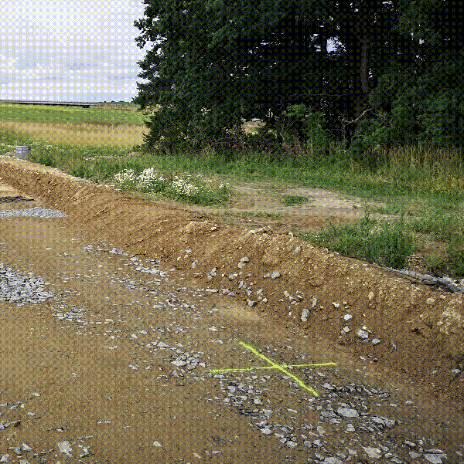
To the naked eye, a GCP might look like a large checkerboard mat, a spray-painted X, or even an improvised cross made from whatever high-contrast material is at hand. To the photogrammetry software processing the drone data, however, that pattern is a beacon. And one principle overrides everything else: “It can be ugly, but its center must be clearly visible.”
The software needs to identify the exact center pixel of each target across multiple overlapping photos. Everything else, like the material, the shape, and the overall tidiness, is secondary. That said, a few properties are non-negotiable:
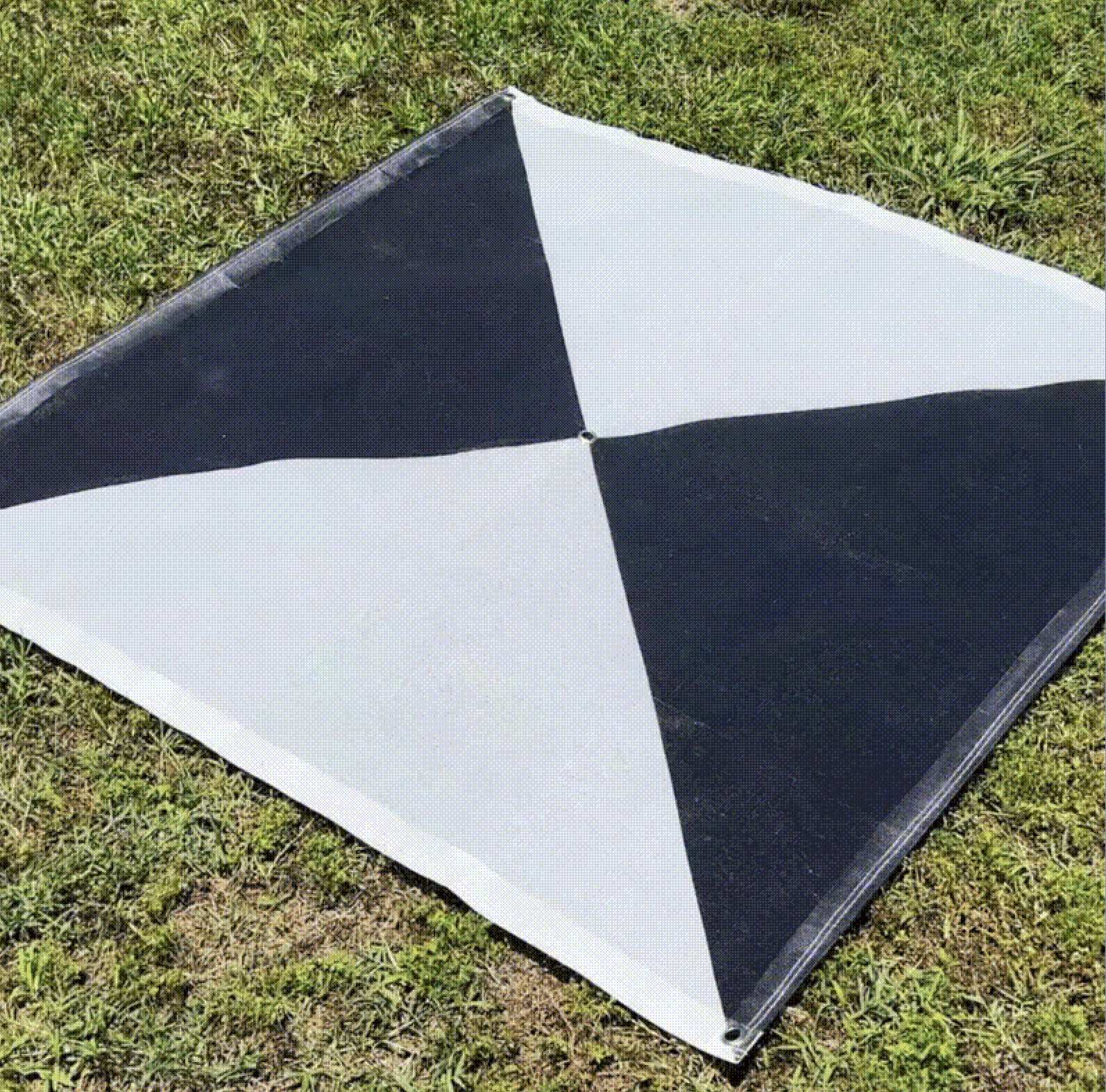
High contrast: The target must stand out sharply from its surroundings. Black-and-white checkerboard patterns are the classic choice because the algorithm can locate the intersection with precision. Spray paint works just as well in practice, but color selection matters enormously. Green spray on a light surface or red on brown soil are nearly invisible from altitude. What looks vivid standing on the ground is often barely detectable from a drone. For example, white on dark asphalt is far more reliable.
Correct size relative to your GSD: A target that is too small for your flight parameters simply won’t resolve clearly enough for the software to use. Use these guidelines based on your Ground Sample Distance:
1 cm/pixel | 20–30 cm |
2 cm/pixel | 40–60 cm |
5 cm/pixel | ~1 meter |
For spray-painted crosses specifically, a simple rule applies: multiply your GSD by 3 to get the correct line thickness. At GSD 1 cm, each arm of your cross should be at least 3 cm wide, thin enough to define the center clearly, thick enough to resolve in the imagery.
Durability and stability: Whatever the material, it must stay flat and unmoved by wind or rotor wash throughout the flight. A target that shifts between passes introduces error rather than correcting it.
A target becomes a useful GCP only when a surveyor measures its exact center using high-precision GNSS tools, assigning a specific coordinate to that point. Until then, it is just a shape on the ground.
Relative vs. absolute accuracy: Why a map that holds its shape can still be dangerously wrong
When you finish assembling a jigsaw puzzle of the United States on your coffee table, Florida is perfectly shaped and sits exactly the right distance from Maine. This internal consistency is called relative accuracy. In drone mapping, achieving it means the distance between two fence posts on your digital map is proportional to the real world, and building shapes are square rather than skewed.
But simply having a map that holds its shape isn’t enough for professional surveyors. If you were to take that completed puzzle and glue it down over the Pacific Ocean on a globe, the puzzle itself would remain perfect, but its position would be completely wrong. This is a lack of absolute accuracy: your digital project doesn’t align with the planet’s actual coordinate system.
Georeferencing drone imagery bridges this gap. Without it, the GPS on a standard commercial drone is only accurate to within a few meters, which is good enough for a hobbyist, but on a construction site, a “few meters” of drift means you might be digging a foundation in your neighbor’s backyard. GCPs force the software to drag that drifting map onto the exact coordinates where it belongs.
Beyond fixing location drift, GCPs also correct scale and size. Photogrammetry software can sometimes struggle with depth perception, creating a subtle “funhouse mirror” effect where terrain warps or tilts. By providing known points with exact elevations, surveyors eliminate these scaling errors: the software calibrates the entire model using the known distances between GCPs, ensuring a 100-foot wall measures exactly 100 feet and not 98 or 102.
How many GCPs do you actually need?
When it comes to GCP count, more is genuinely better. The minimum requirements scale with the size of your project:
Small areas (up to 1 ha): At least 5 GCPs, evenly distributed, four near the corners and one in the center.
Medium areas (1–10 ha): 5–10 GCPs, placed at corners, along edges, and one or two in the interior.
Large areas (10–100 ha): A minimum of 10–20 GCPs, with the density increasing as terrain complexity increases.
These are floors, not targets. On sites with significant elevation change, dense vegetation, or complex geometry, add more. Before every new construction project, it is worth dedicating real time to planning where points will go, not just how many. That pre-flight planning is the difference between data that looks plausible and data a client can build from.
Two practical rules that experienced surveyors follow regardless of area size: always add at least two extra points beyond your calculated minimum for every 500 photos in the dataset (you never know which points will be obscured or measured with an error), and on dense GCP networks, label each target in the field with a number or letter so there is no ambiguity when entering coordinates in the office.
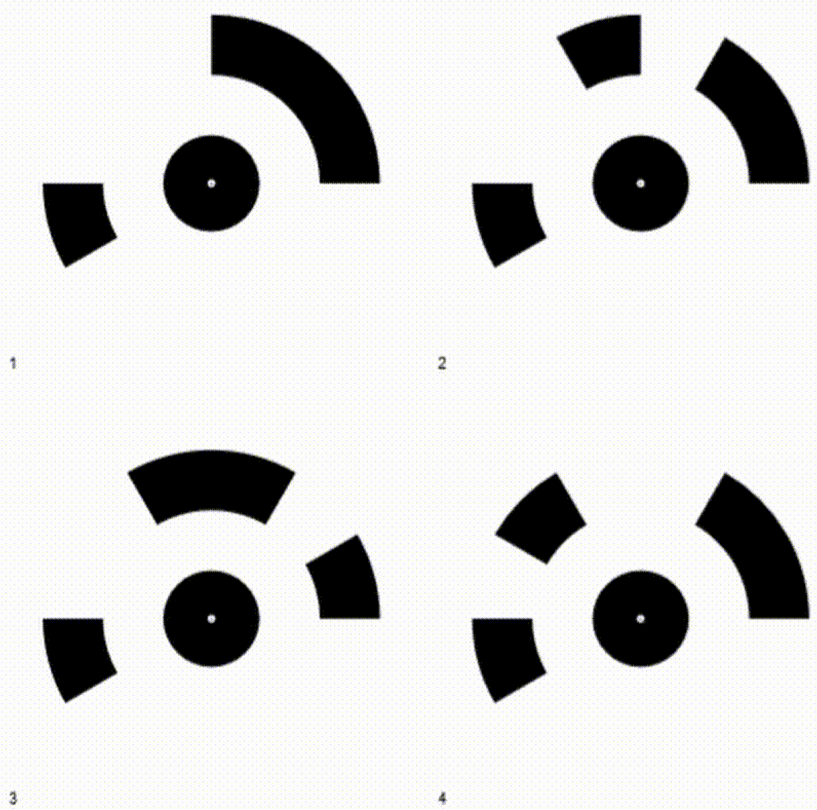
Four coded GCP targets, each encoding a unique ID in its petal pattern. The center dot is the measurement point
How professionals place and measure GCPs to achieve centimeter precision
To turn theoretical accuracy into a usable map, you have to get your boots dirty.
The first step is distributing targets across the project area. The material matters less than visibility: the goal is a pixel-perfect center that a drone flying 60 meters overhead can easily distinguish from surrounding grass, dirt, or asphalt. Checkerboard vinyl mats are the professional standard; spray-painted crosses on pavement or compacted earth are a fast and effective alternative when done with the right color and line width (see the sizing guidance above).
Next, each target’s center must be measured using a GNSS receiver. Unlike a smartphone GPS, which might wander within a 15-foot radius, a professional rover records a latitude, longitude, and elevation accurate to the width of a fingernail.
The complete workflow follows this sequence:
Place: Distribute visual markers across the site’s boundaries and center
Measure: Record the exact center of each marker using high-precision GNSS
Fly: Capture aerial imagery ensuring every marker appears in multiple overlapping photos
Stitch: Import photos and coordinate data into photogrammetry software
Verify: Use check shots (targets not used in processing) to validate final accuracy
During the final processing stage, the software locates those targets in the photos and anchors the digital map to the real-world coordinates you recorded on the ground.
Technical note: If you are conducting repeated drone surveys at the same location and need to establish new GCPs each time, correct your measured values to a baseline. This ensures consistency between survey epochs and prevents small measurement variations from introducing drift into your change-detection analysis.
The bowling effect: Why GCP placement matters as much as the count
Imagine stretching a fitted sheet over a mattress. If you secure the four corners but leave the middle loose, the fabric puffs up in the center. In photogrammetry, this is called the “bowling effect.” Place your GCPs only at the perimeter of a site, and the digital model will likely suffer from vertical drift: the center appearing several feet higher or lower than it actually is.
The fix is the dice pattern. Just like the five-pip side of a standard die, place a control point in the geographic center of your project area. This central anchor ties the “belly” of the map to the earth, keeping the 3D model flat and true. For larger or irregularly shaped sites, replicate this triangulation logic so that no large area is left without a nearby anchor.
Follow these four principles when distributing your points:
Secure the perimeter: Place markers near corners, but 10–15 feet inward so they appear in plenty of photos
Pin the center: Never leave the middle of the site empty; this is where the most drift occurs
Capture elevation changes: On sites with hills or pits, place markers at the highest and lowest points
Check visibility: Ensure no parked vehicles, trees, or equipment will block the drone’s view of the target
For linear projects like roads, pipelines, or corridors, the standard distribution logic doesn’t apply as cleanly. In these cases, increase the photo overlap per point, aiming for at least 10 images per GCP, to give the software enough geometry to anchor the model along the full length of the feature.
Flight conditions matter too
One variable that doesn’t get enough attention: lighting. Photogrammetry software struggles when the same scene is photographed under different light conditions. Shadows shift, colors change, and the software has a harder time matching features between images. Where possible, complete the entire flight in a single day and within as short a window as practical. A dataset captured in consistent flat light will process more cleanly than one split across a morning and an afternoon, even if all other parameters are identical.
On the same note: oblique images have their uses, but perpendicular (nadir) photography is the foundation of any accurate mapping flight. Always ensure your primary pass is nadir before adding any oblique coverage.
RTK drones vs. GCPs: Why high-tech onboard GPS still needs ground verification
Modern drone marketing often claims that Real-Time Kinematic (RTK) technology has made manual GCPs obsolete. RTK upgrades standard GPS to centimeter-level precision by communicating constantly with a stationary base station, tagging every photo with exact coordinates the moment the shutter snaps.
But relying solely on the aircraft’s positioning introduces a risk known as “floating data.” Atmospheric interference or momentary signal drops can still cause the resulting map to shift slightly relative to the real world. Without physical anchors on the ground to verify alignment, you might generate a highly detailed 3D model that floats six inches above the actual earth, which is useless for tasks like pouring concrete or establishing property boundaries.
Professional surveyors solve this with checkpoints: independently measured ground targets that are not used in the stitching process, but instead used to grade the result afterwards. If the digital map lands accurately on the checkpoint’s known coordinates, the data is validated. If it misses, you know the aerial signal drifted, and correction is needed.
RTK drastically reduces the number of targets you need to place, but it never eliminates the need for independent verification. A map without checkpoints is an unverified claim. A map with them is a certifiable engineering tool.
Your pre-flight checklist for a high-accuracy drone survey
By mastering GCPs, you transform drone photos into engineering-grade deliverables. In construction or disaster response, the difference between relative and absolute accuracy is the difference between a safe structure and a costly lawsuit.
Before your next flight, run through this checklist:
Equipment check: Confirm your GNSS rover and targets are calibrated and ready.
Color and size check: Verify your targets are the right size for your planned GSD and high-contrast against the actual surface they’ll sit on, not just in theory.
Site scouting: Walk the area to identify safe, unobstructed target locations; note any potential obstructions.
Distribution plan: Place markers near corners and the center; add extras for elevation changes; never arrange them in a straight line.
Labeling: Number or letter each target in the field if using a dense network.
Measurement: Record the exact center coordinates of every target; add at least two spare points per 500 photos.
Flight conditions: Plan to complete the flight in one session under consistent lighting.
Verification: Use check shots not included in processing to prove accuracy afterward.
The extra setup time pays for itself the moment you hand a client a map accurate to the centimeter—one they can build from, not just look at.
What to read next
Photogrammetry software: Complete guide to AVAG for construction, mining, and infrastructure teams
FPV drones in 2026: The technology changing aerial filmmaking
What are Ground Control Points (GCPs), and why should you use them for drone mapping?
What is geospatial data? Collection, analysis, and how to use it
See what your geospatial data can really do
Join more than 1,000 satisfied users. Just upload your files and see results.
No credit card required
About the author

Marek Ruzek
CTO at AVAG Pro
Marek Ruzek is the CEO and co-owner of AirView s.r.o. and the CTO behind AVAG, a cloud platform built for construction and surveying professionals working with drone data, photogrammetry, and 3D geospatial workflows. With nearly a decade leading AirView, he has been at the forefront of bringing drone-data technology to major infrastructure projects across the Czech Republic, including the D3 highway, the PPP D4 project, and large-scale earthworks monitoring.
Subscribe and do not miss latest posts
Blog
Explore more articles