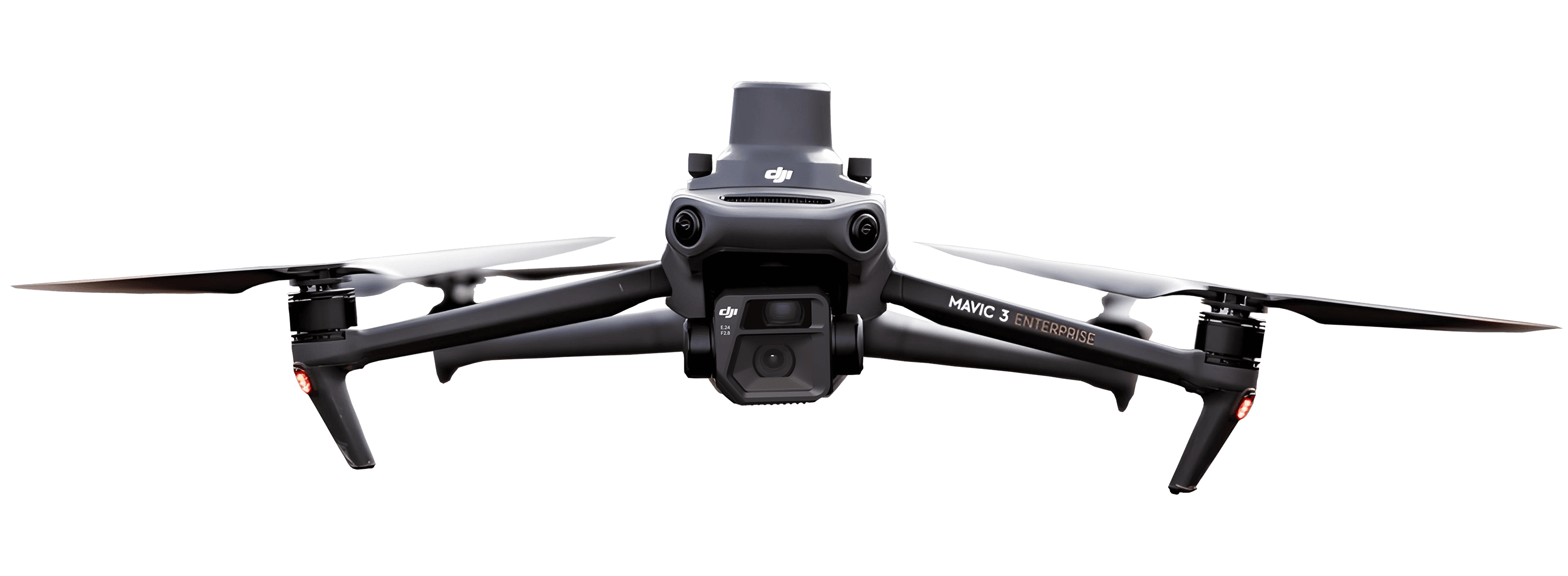
Integrating drone data with CAD drawings for site analysis
Updated:
Why wait days for a surveyor when your drone can update the site plan by afternoon?

You have a drone orthomosaic showing current site conditions. You have a CAD drawing showing the design. Getting them to line up correctly is where most teams get stuck.
The fix comes down to coordinate systems and file formats. When both match, you can overlay as-built terrain on design linework and spot grading errors, verify contractor quantities, and track progress without waiting for a surveyor. This guide walks through the complete workflow, from flight to analysis, along with the file formats, alignment steps, and common problems you will encounter.
Why integrate drone data with CAD drawings on construction sites
Integrating drone data with CAD drawings comes down to two things: matching coordinate systems and using the right file formats. When both pieces align, you can overlay drone-captured site conditions directly onto your design linework. The result is a visual comparison between what was planned and what actually exists on the ground.
This comparison is where the real value shows up. Instead of waiting days for a surveyor to walk the site and deliver updated conditions, you can fly a drone in the morning and see current terrain layered over your design by afternoon. Grading errors become obvious. Contractor quantities become verifiable. Progress becomes measurable.
Design vs. reality comparison: Spot where actual terrain deviates from planned grades
Contractor verification: Check quantities before approving payment applications
Progress documentation: Build a visual record of how the site evolves over time
Reduced survey bottlenecks: Update site conditions without scheduling a ground crew
Types of drone data used in CAD workflows
Drones capture raw photos. Photogrammetry software then converts those photos into several output types, each serving a different purpose when combined with CAD drawings.
Orthomosaics and aerial imagery
An orthomosaic is a stitched aerial image where each pixel has real-world coordinates. The geometry is corrected so measurements taken on the image reflect actual distances on the ground. Think of it as a high-resolution base map that sits behind your CAD linework, giving visual context to every design element.
When you overlay a DWG file on an orthomosaic, you immediately see whether as-built conditions match the design. A road centerline that drifts from the planned alignment becomes visible at a glance.
Digital surface and terrain models
A digital surface model (DSM) captures everything visible from above: buildings, vegetation, stockpiles, equipment. A digital terrain model (DTM) represents bare earth only, with surface objects filtered out.
Both are raster elevation models, meaning each pixel stores an elevation value. When you compare a DTM against a CAD design surface, you get cut/fill calculations showing where material needs to be removed or added.
Point clouds from photogrammetry and LiDAR
A point cloud is millions of XYZ coordinate points representing surface geometry. Each point has a position in three-dimensional space, and together they form a detailed representation of the site.
Point clouds can be imported into Civil 3D, Revit, or similar CAD software for detailed modeling. They capture complex geometry that 2D drawings cannot represent, which makes them useful for clash detection and as-built documentation.
Contour lines and vector outputs
Contour lines and breaklines can be extracted from DSMs and exported as DXF or DWG files. This bridges the gap between raster drone outputs and vector CAD workflows. You can bring drone-derived topography directly into your design environment without manual tracing.
File formats that connect drone outputs to CAD drawings
File format compatibility determines whether drone data will actually open in your CAD software. Here are the formats you will encounter most often:
Format | Data type | Used for | Compatible with |
|---|---|---|---|
DWG/DXF | Vector linework | Design drawings, contours | AutoCAD, Civil 3D, BricsCAD |
LandXML | Surfaces, alignments | Grading plans, road corridors | Civil 3D, Trimble Business Center |
LAS/LAZ | Point clouds | 3D site geometry | ReCap, CloudCompare, Civil 3D |
GeoTIFF | Georeferenced images | Orthophoto underlays | QGIS, Global Mapper, CAD with raster support |
IFC | BIM objects | Model coordination | Revit, ArchiCAD, Navisworks |
DWG and DXF are standard CAD formats. Your drone platform can import DWG/DXF files so you can overlay design linework on top of orthophotos. LandXML carries TIN surfaces and road alignments, allowing direct comparison between drone-derived surfaces and design surfaces.
LAS is the standard point cloud format. LAZ is the compressed version. Point clouds are often too large for standard CAD software and may require specialized viewers or decimation before import. GeoTIFF embeds coordinate information in the image file, so the orthophoto positions itself correctly when imported.
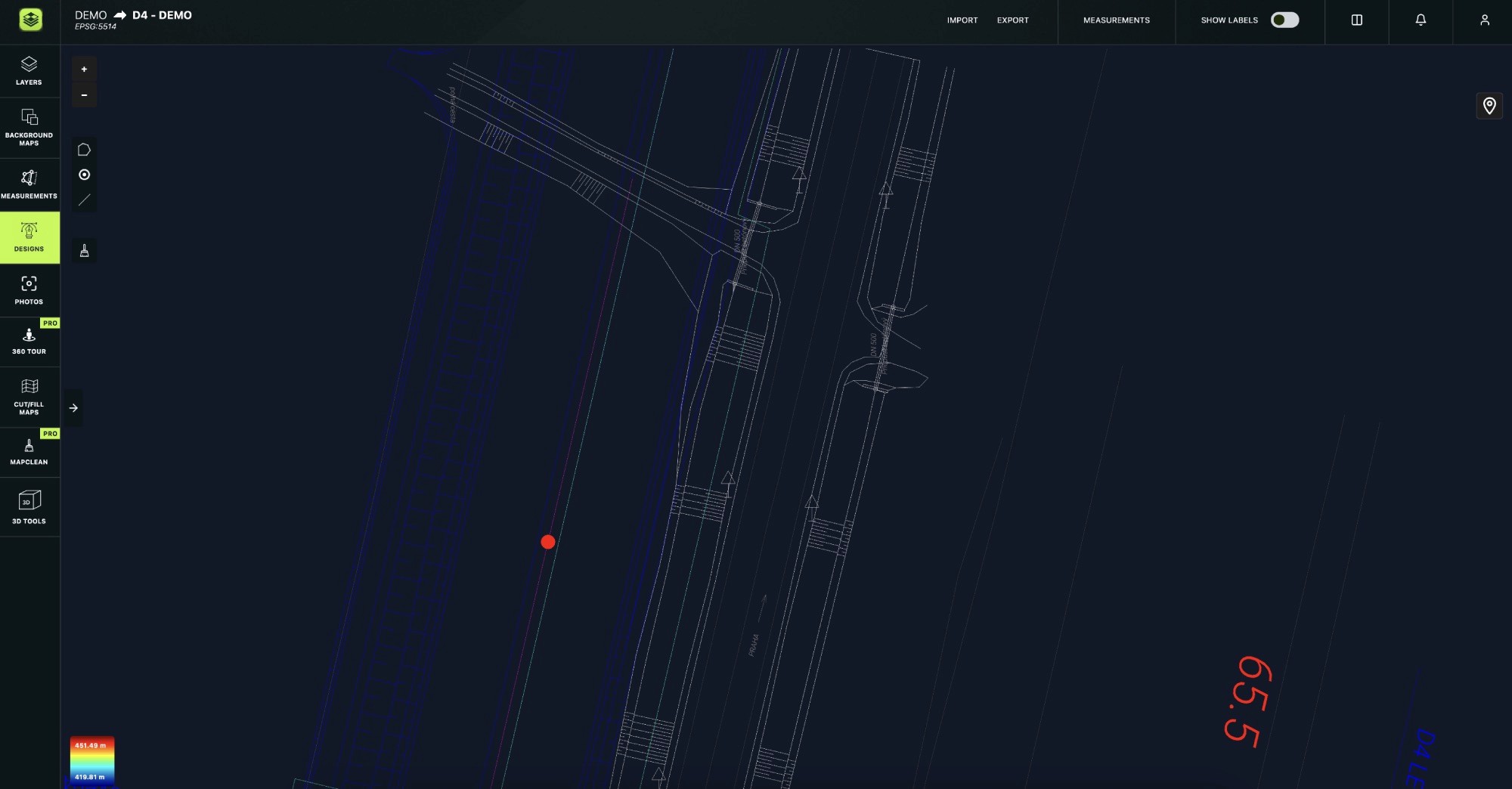
DXF inside the AVAG platform
How to integrate drone data with CAD drawings step by step
Step 1: Capture the site with a georeferenced drone flight
Plan your mission with 70–80% front overlap and 60–70% side overlap. RTK drones or ground control points (GCPs) provide the accuracy needed to match CAD coordinates. Without proper georeferencing, your drone data will shift or scale incorrectly when you try to align it with design drawings.
Step 2: Process photos into orthomosaics, DSMs, and point clouds
Upload your raw images to photogrammetry software for processing. The software stitches photos into outputs using structure-from-motion algorithms. AVAG offers both automated processing and expert-reviewed processing.
Step 3: Match coordinate systems between drone outputs and CAD
Your drone data and CAD drawings need to share the same coordinate reference system (CRS). Common systems include local grid coordinates, UTM zones, or state plane coordinates. If the CRS does not match, your overlay will be misaligned even if both datasets are individually accurate.
Step 4: Import CAD drawings as a layer over drone data
Upload your DWG or DXF file and position it over the orthophoto. Cloud platforms like AVAG allow this without requiring AutoCAD licenses for every team member. The design linework appears directly on top of current site conditions.
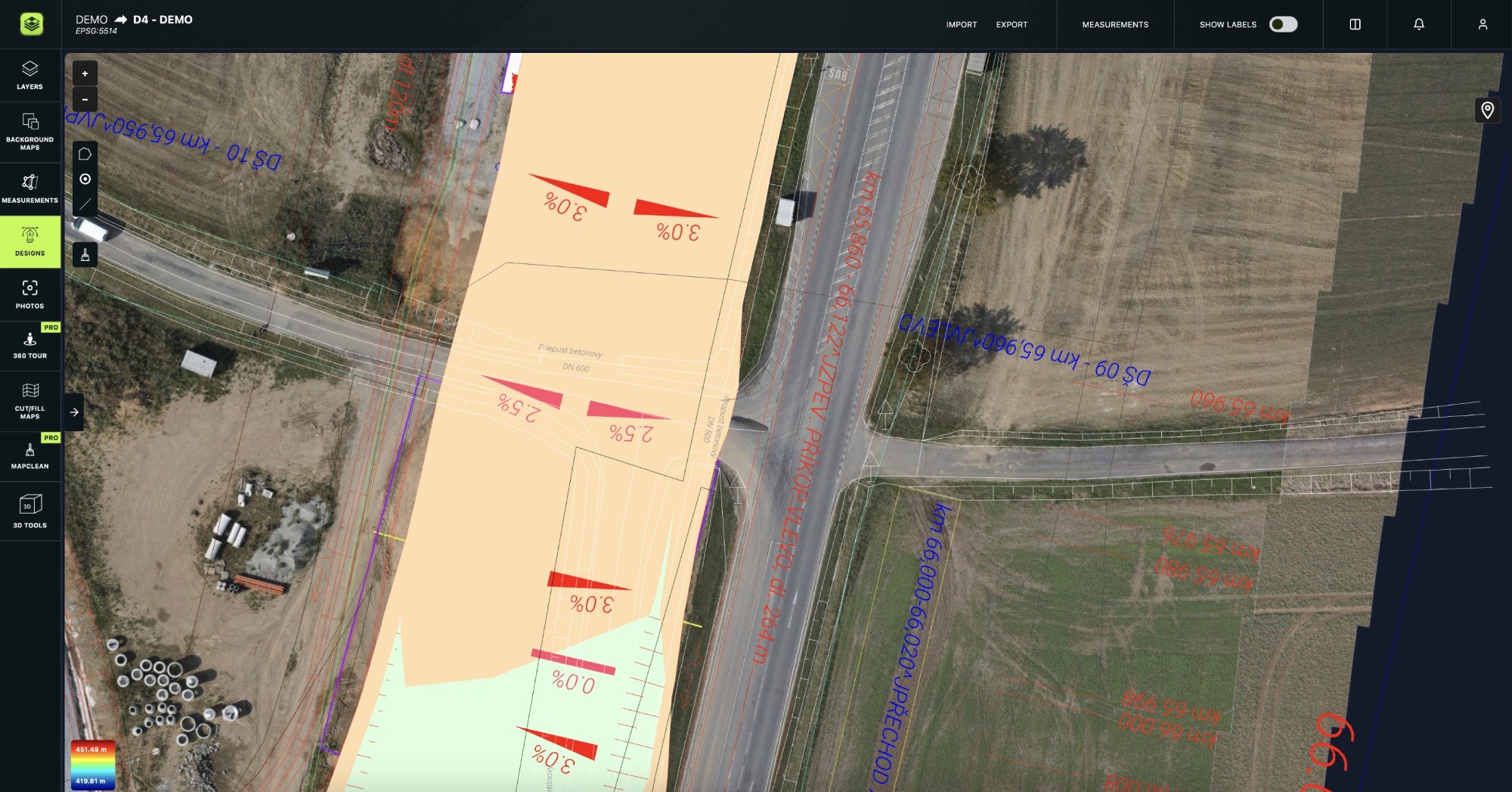
DXF combined with an orthophoto inside the AVAG platform
Step 5: Run volumes, cut/fill, and as-built comparisons
Compare the drone-derived surface to the CAD design surface. The result appears as a color-coded cut/fill map showing where material needs to be removed or added. Volume reports and as-built verification outputs follow from this comparison.
Site analysis you can run on a drone and CAD overlay
Once drone data and CAD are aligned, several analysis types become possible.
Cut and fill against design grade
Comparing the drone-derived surface to the CAD design surface shows where material needs to be cut (removed) or filled (added). The result typically appears as a color-coded map with red indicating cut areas and blue indicating fill areas. This tells you exactly how much earthwork remains before the site matches the design.
Volume calculations for stockpiles and excavations
You can calculate material volumes by comparing surfaces or measuring stockpile geometry against a base plane. This supports invoice verification for hauling and earthworks contracts, where payment depends on accurate quantity measurement.
As-built verification and contractor quantities
Overlaying drone data on CAD drawings confirms that built conditions match specifications. A road subgrade that sits 5 cm too high becomes visible when compared against the design surface. This supports quantity takeoffs and payment applications by providing visual evidence of completed work.
Progress tracking across survey dates
Comparing multiple drone surveys over time, overlaid on the same CAD drawing, shows construction progress. Storing each survey as a dated version enables before/after comparisons. When disputes arise about when work was completed, you have dated visual evidence.
Common problems when combining drone data with CAD drawings
Coordinate system mismatch: The most frequent cause of misalignment. Verify CRS before processing.
GCP accuracy limitations: Poor GCP placement or measurement degrades overall accuracy.
Point cloud file size: Large point clouds crash CAD software or slow performance.
Outdated CAD drawings: Design revisions not reflected in the file being used for comparison.
Missing georeferencing: Some CAD drawings lack real-world coordinates entirely.
Best practices for accurate drone and CAD integration
Use ground control points on every flight
GCPs matter for accuracy even with RTK drones. Spread them across the site rather than clustering them in one area. Four to six well-distributed GCPs typically provide better results than ten points grouped together.
Standardize coordinate systems across projects
Establish a single CRS for all project data at the start. Agree on this with surveyors, engineers, and contractors before the first flight. Changing CRS mid-project creates alignment headaches that compound over time.
Keep point clouds lightweight for CAD software
Decimation and thinning reduce point cloud density for CAD import. Cloud platforms can handle full-resolution data while exports to desktop CAD are simplified for performance. You keep the detail where you need it without crashing your workstation.
Version surveys so teams can compare over time
Store each survey as a dated version. This enables progress tracking, quantity verification across time periods, and documentation for dispute resolution. When someone asks what the site looked like three weeks ago, you have the answer.
Sharing drone and CAD overlays with field, office, and client teams
Traditional workflows lock data with one person who owns CAD software. Everyone else waits for exports, screenshots, or meetings to see current conditions.
Cloud platforms change this by enabling view-only access for stakeholders who need to see data but do not need to edit. Permission controls let you share specific project areas with specific people. AVAG includes unlimited users at no per-seat cost, so you can share with everyone involved without worrying about license fees.
Site managers: View orthophoto with CAD overlay on mobile device
Project engineers: Run cut/fill analysis in browser without CAD license
Clients: Access progress photos and volume reports via shared link
Subcontractors: Review their work areas with permission-limited access
Turn drone and CAD data into same-day site decisions with AVAG
AVAG combines drone data, scanner data, 360° imagery, and CAD drawings in one project.
The platform offers both automated processing and expert-reviewed processing for difficult sites. Data is stored on EU-based servers, and the interface is available in six languages. Try AVAG for free.
Frequently asked questions about integrating drone data with CAD drawings
Can I overlay a DWG file on a drone orthomosaic without AutoCAD?
How accurate is drone photogrammetry compared to traditional ground survey for CAD integration?
Do I need ground control points if my drone has RTK GPS?
Which coordinate reference system should I use when combining drone data with CAD drawings?
See what your geospatial data can really do
Join more than 1,000 satisfied users. Just upload your files and see results.
No credit card required
About the author

Miroslav Staubr
CEO at AVAG Pro
Miroslav Staubr is the CEO and co-owner of AirView s.r.o. and the product lead behind AVAG, a cloud platform used across construction and surveying for processing drone, LiDAR, and 3D geospatial data. As a certified drone pilot with the highest permit for aerial mapping, he brings hands-on experience working with UAVs (Unmanned Aerial Vehicles), commonly known as drones, to capture precise data for photogrammetry, terrain analysis, and earthwork volume calculations.
Subscribe and do not miss latest posts
Blog
Explore more articles

What does “photogrammetrically” mean? A plain explainer
Learn what “photogrammetrically” means and how photos become accurate 3D site measurements.
Read more

How do drone service providers deliver data to clients securely?
Your drone data includes GPS coordinates, site layouts, and project timelines—do you know exactly who can access it?
Read more